Introducing the Self-sustaining
Two Dimensional,
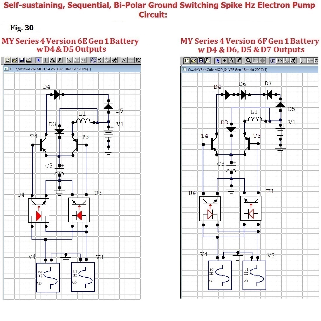
Sequential, Bi-Polar Ground Switching Spike Hz Electron Pump Circuit
that are Well Beyond What They All Knew
Two Dimensional,
Sequential, Bi-Polar Ground Switching Spike Hz Electron Pump Circuit
that are Well Beyond What They All Knew
There is a fundamental operational concept concerning any Third Principle's Two Dimensional circuit, and it is critical to comprehend both this concept and how its fundamental operation is, literally random.
Series 4 Version 6F CIRCUIT ASSEMBLY (33 of 33)
Series 4 Version 6F CIRCUIT ASSEMBLY (33 of 33)
More
on Assembling (33 of 33) the
Sequential, Bi-Polar Ground Switching Spike Hz Electron Pump
Series 4 Version 6F CIRCUIT ASSEMBLY Instructions (33 of 33)
More
on Assembling (33 of 33) the
Sequential, Bi-Polar Ground Switching Spike Hz Electron Pump
Series 4 Version 6F CIRCUIT ASSEMBLY Instructions (33 of 33)
junction
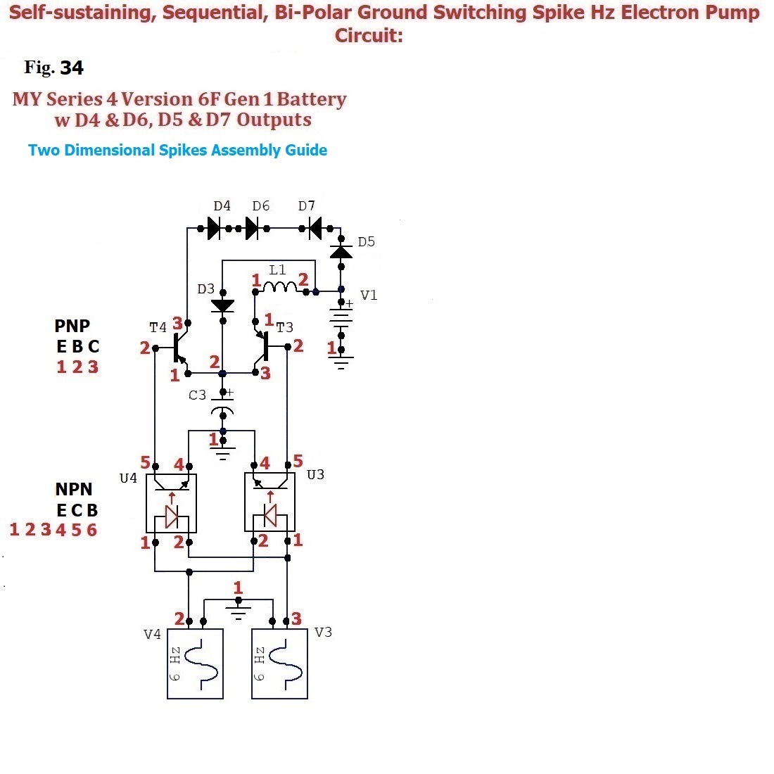
{01} is where the Oscillator's V3-1 and V4-1 are each commonly connected with either the Circuit Board Trace or a #23 Wire to Ground
then, after a break, connect U3-1 with either a Circuit Board Trace or a #23 Wire to U4-2
and then, after another break, connect Oscillator's V3-3 with either a Circuit Board Trace or a #23 Wire to the OptoIsolator's U4-2 and U3-1 span
then, after a break, connect U3-2 with either a Circuit Board Trace or a #23 Wire to U4-1
and, after another break, connect Oscillator's V4-2 with either a Circuit Board Trace or a #23 Wire to the OptoIsolator's U4-1 and U3-2 span
junction
{02} is where OptoIsolator's U3-4 and U4-4 and Negative C3 are each connected with either Circuit Board Traces or a #18 Wires to Ground
and then, after a break, connect OptoIsolator's U3-5 with either a Circuit Board Trace or a #18 Wire to T3-2
and, after another break, connect OptoIsolator's U4-5 with either the Circuit Board Trace or a #18 Wire to T4-2
junction
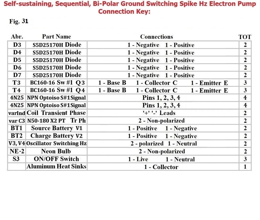
{03} is where the Positive terminal of C3 and 4N25's T3-3 and 4N25's T4-1 and the Negative terminal of D3 are each commonly connected with either Circuit Board Traces or #18 Wires
and, after a break, connect the Source's Battery Positive with either the Circuit Board Traces or #18 Wire and L-2 with either the Circuit Board Trace or #18 Wire and the Positive terminal of D5 with either the Circuit Board Trace or #18 Wire to form the junction {04} span
junction
{04} is the Source Battery Positive's span where the following individual paths eventually converge:
Then, after a break, D3's Positive terminal continues with either a Circuit Board Trace or #18 Wire to the Source Battery Positive's span, (or junction {04})
and, after another break, continue from the 4N25's T3-1 terminal with either a Circuit Board Trace or #18 Wire to the Coil's L-1 terminal
and, after another break, the continuation from the Coil's L-2 terminal with either a Circuit Board Trace or #18 Wire should have already been attached to the Source Battery Positive's span
and, after another break, continue from 4N25's T4-3 with either a Circuit Board Trace or #18 Wire to the Positive of D4
and, after another break, continues on from the Negative of D4 with either a Circuit Board Trace or #18 Wire to the Positive of D6
and, after another break, continues on from the Negative of D6 with either a Circuit Board Trace or #18 Wire to the Negative of D7
and, after another break, continues on from the Positive of D7 with either a Circuit Board Trace or #18 Wire to the Negative of D5
and, after another break, continuing on, the Positive of D5 should already have been connected with either a Circuit Board Trace or #18 Wire to the Source Battery Positive's span
Copper
Winding Wires
#23 and #18 Copper Wires
Aluminum Heat Sinks
The new and even deeper perspective of chaos' Energy, is also like Bedini's School Girl Motor/Generator, is also produced in the Transient Phase of the VL Spikes, isolated, captured and released back into the Source Battery, and all these in their proper Time
Part 3, Series 4 Version 2A CIRCUIT ASSEMBLY (31 of 33)
Part 4, Series 4 Version 5D CIRCUIT ASSEMBLY (32 of 33)

Either any of my Transient Phase Simulations or the CircuitMaker Program are using Excel
(or Spreadsheet type techniques) for their intense calculations.
It is, therefore, advisable and wise to know Three things:
Any of these resources files can be corrupted if your
computer's resources are over-taxed.
and a requirement to use any of the Transient Phase Simulations is to have Excel or an equivalent.
Preserve Original File, and Work only from a backup to avoid File corruption when using these resources, and be vigilant protecting your work.
Return
Home
(or Spreadsheet type techniques) for their intense calculations.
It is, therefore, advisable and wise to know Three things:
Any of these resources files can be corrupted if your computer's resources are over-taxed.
and a requirement to use any of the Transient Phase Simulations is to have Excel or an equivalent.
Preserve Original File, and Work only from a backup to avoid File corruption when using these resources, and be vigilant protecting your work.