eternaltruth.net

The Electric Car

Copyright © 2008, E C Distributions


Welcome to a realm reaching beyond what science is willing to accept.


Our goal has been a Circuit capable of powering an Electric Car and that also charges its source. Such claims have been made, yet the realities of these claims are both ignored by academia and buried in mythical stories with no visible proof. One of those stories is that John Bedini's research and presentations inspired Ronald Brandt to build the following circuit and Bedini also declared the same car could be driven all over town. When Bedini asked for Brandt's permission to publicly share the circuit, Brandt stated the circuit was not his own design, but was rooted in Bedini's concept of Tesla. Herein the myth and myths of the Tesla myth were reborn.

If Energy is being wasted in inefficient processes, and a part of that wasted Energy is being reclaimed by placing one set of the two sets of similar polarity batteries in series, powering a load, charging two batteries of the same type in the second parallel set, is the degree of Efficiency being increased if the two alternating sets of batteries are mysteriously charging themselves?


From the details seen in the schematic there is no evidence the Tesla influence on Bedini is actually present. References to the design introduce the concept of Switch #1, and then go on to elaborate that there are not only at least six Switches, and these at least six Switches may be either Mechanical or Electronic, and these at least six Switches have a Control Timing Pulse to create a VL Spike.

A closer examination reveals there is a high Inductance motor (acting as the Coil), and Switch #1 is identified as any Switch(es) that shut(s) off the flow of V and Current at the Inductor/Motor's Negative or Ground. Essentially these (likely two) Switches are Bedini's Switch #1. So, as you design your build with these facts in mind, you will also see how Bedini's Timing influences (t's) are implemented to garnish him with credit. This same examination unveils inconsistencies in the schematic presented. It is not feasible to obtain VL Spikes when the Inductor/Motor is not attached to the Circuit's Positive Output. If the VL Spikes were not needed my contributions will make this design even more efficient.

One cannot ignore there is some degree of engineering involved with the Motor's Inductance, and that these values work in concert with the Switch's Timings to create the higher AVE DC from a series of VL Spikes. The Transient Phase Simulation Software may offer assistance.

The challenge begins with there being several different ways to accomplish this design's intentions. Those schematics which follow demonstrate specific designs, and each of them has unique attributes, and it is your responsibility to determine which Power Supply Switching attributes function best. (To my knowledge they are all functional...)


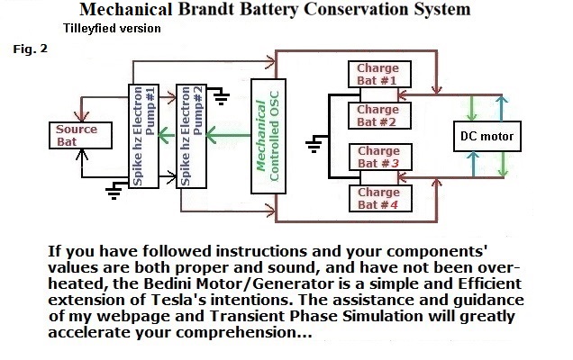
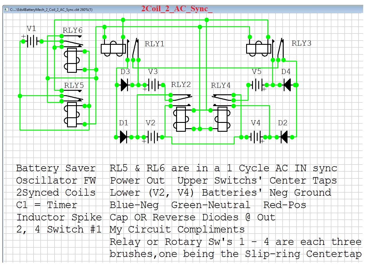
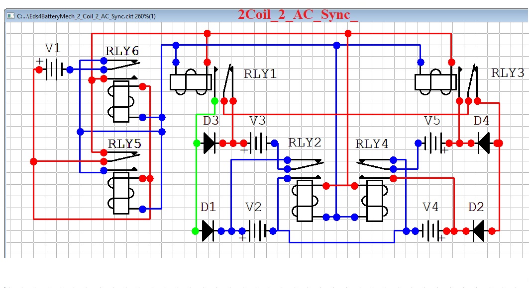
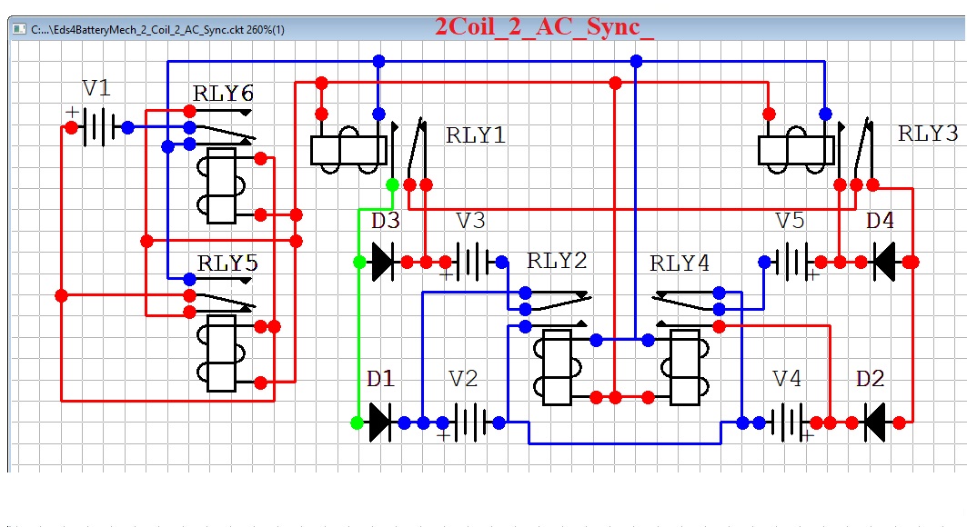
Our first Mechanical Oscillator design has 2 Synced Coils and 2 Cycles, is producing a square wave AC, and is presented in 3 stages.
Blue lines are Negative
Green lines are Neutral
Red lines are Positive


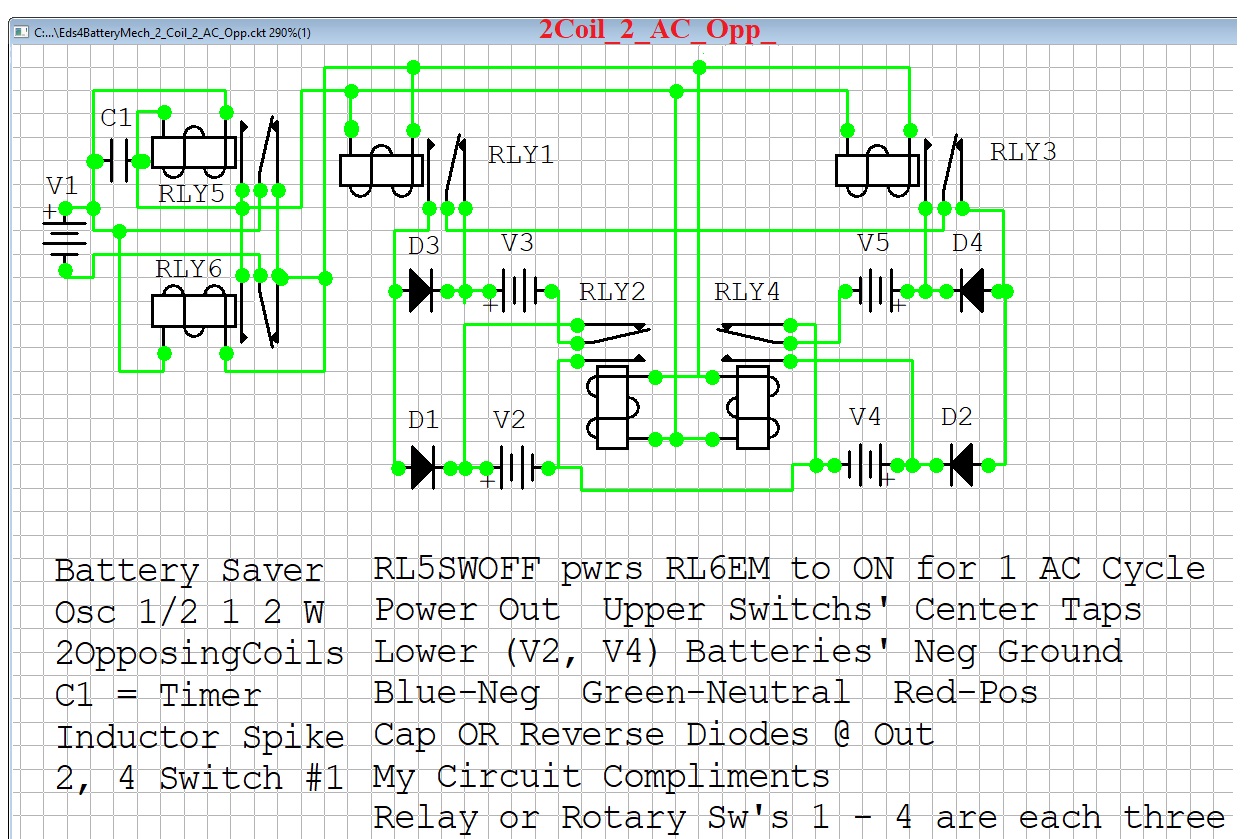
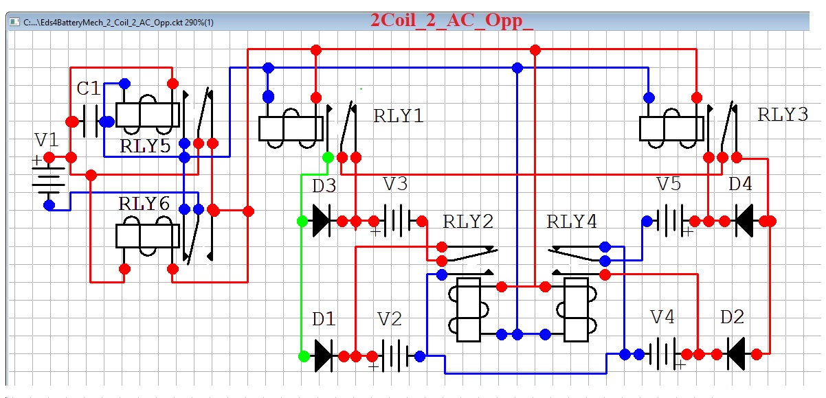
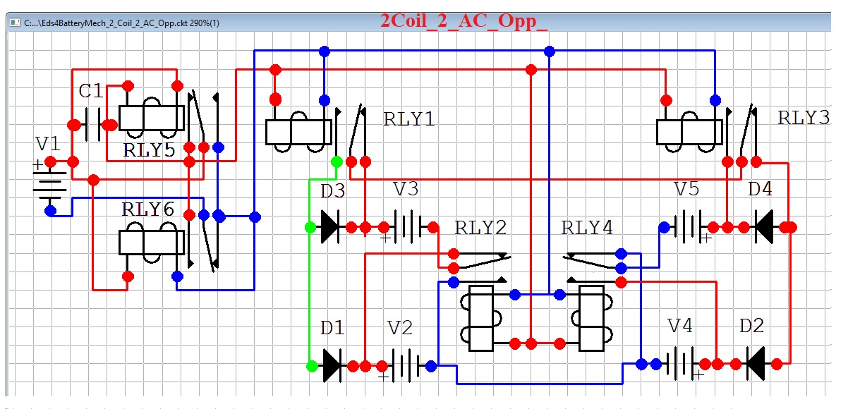
Our second Mechanical Oscillator design has 2 Opposing Coils and 2 Pulse Cycles, is producing a square, Pulsed wave, and is presented in 3 stages.
Blue lines are Negative
Green lines are Neutral
Red lines are Positive


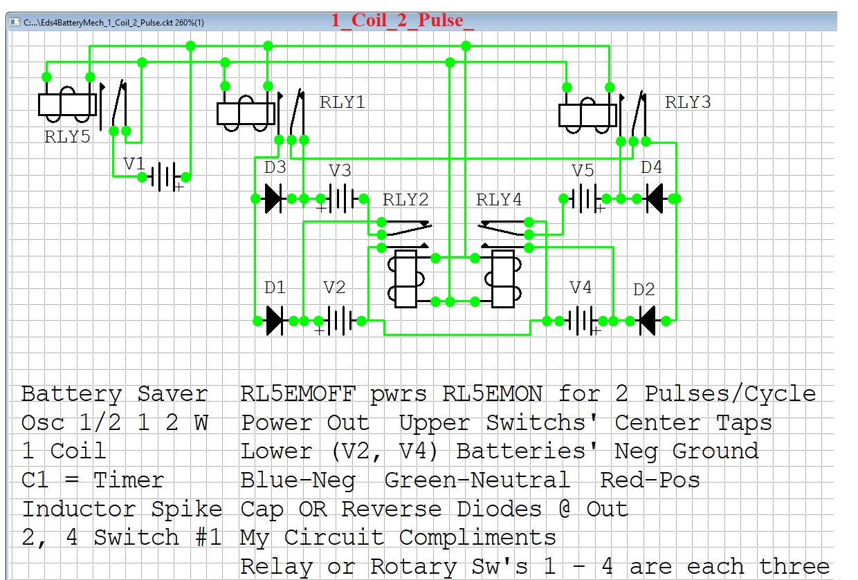
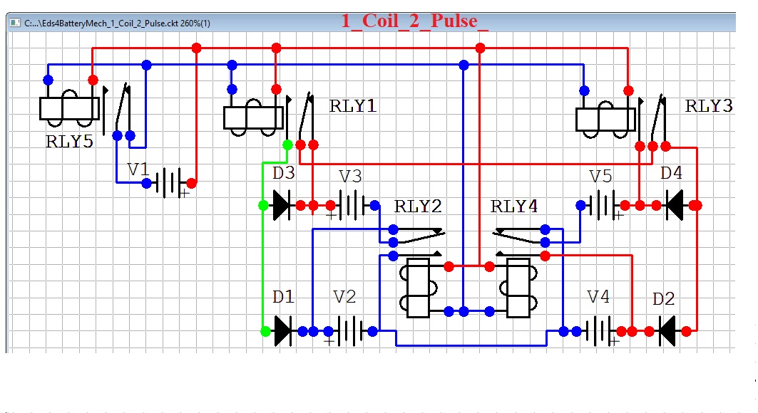
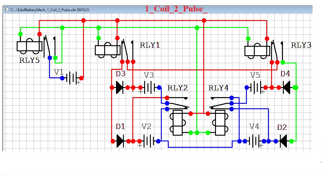
Our third Mechanical Oscillator design has 2 Synced Coils and 2 Pulsed Cycles, is producing a square Pulsed wave, and is presented in 3 stages.
Blue lines are Negative
Green lines are Neutral
Red lines are Positive


Our fourth Oscillator design is the first Digital and has 2 Cycles, is producing a square Pulsed wave, and is presented in 2 stages, the second stage being an animation.
Green lines are Negative
Red lines are Positive


The MICROSEMI SG1524 specs


Blue lines are Neutral
Green lines are Negative
Red lines are Positive


Consider the Energy just described, realizing that these levels of Efficiency are not detected by traditional meters. What would a Timing electronic circuit capable of generating such a transformation with a Switch controlling differing periods and durations reveal? A true scientist has the will to rise above concepts which classical science is not willing to entertain... How would knowledge of a more efficient Energy form that might even sustain itself benefit our world? We tend to think and believe that we have open access to the latest and greatest technologies. Is such true? Most of the world is unaware of those people who have witnessed concepts establishing the truth. Magnetic Fields may well be an undetected symphonic harmony of Energy that is simply not acknowledged by current scientific processes.

If Energy Efficiency is low, and a part of that wasted energy is alternately being reclaimed by one set of two recharging lower Voltage batteries in parallel, which are established as being charged by the other set of two batteries in series for this half cycle. The Switches then reverse the conditions of the two sets such that the series set becomes parallel and the parallel set becomes series, within a cycle where the two sets of batteries are alternatively Switching between these two states where an opposing polarity battery is in series with a load powered by 2 of the same type of batteries in series, Is the degree of efficiency being increased if the batteries charge themselves to any degree?


The simulation requires Excel, or an equivalent.
Preserve Original File,
this Transient Phase Simulation's File can be corrupted
if your computer's resources are over-taxed.
Work only from a backup to avoid File corruption


Return Home