Transient Phase #1's Simulation Instructions
Oscillator Switch #1 Pulse Control

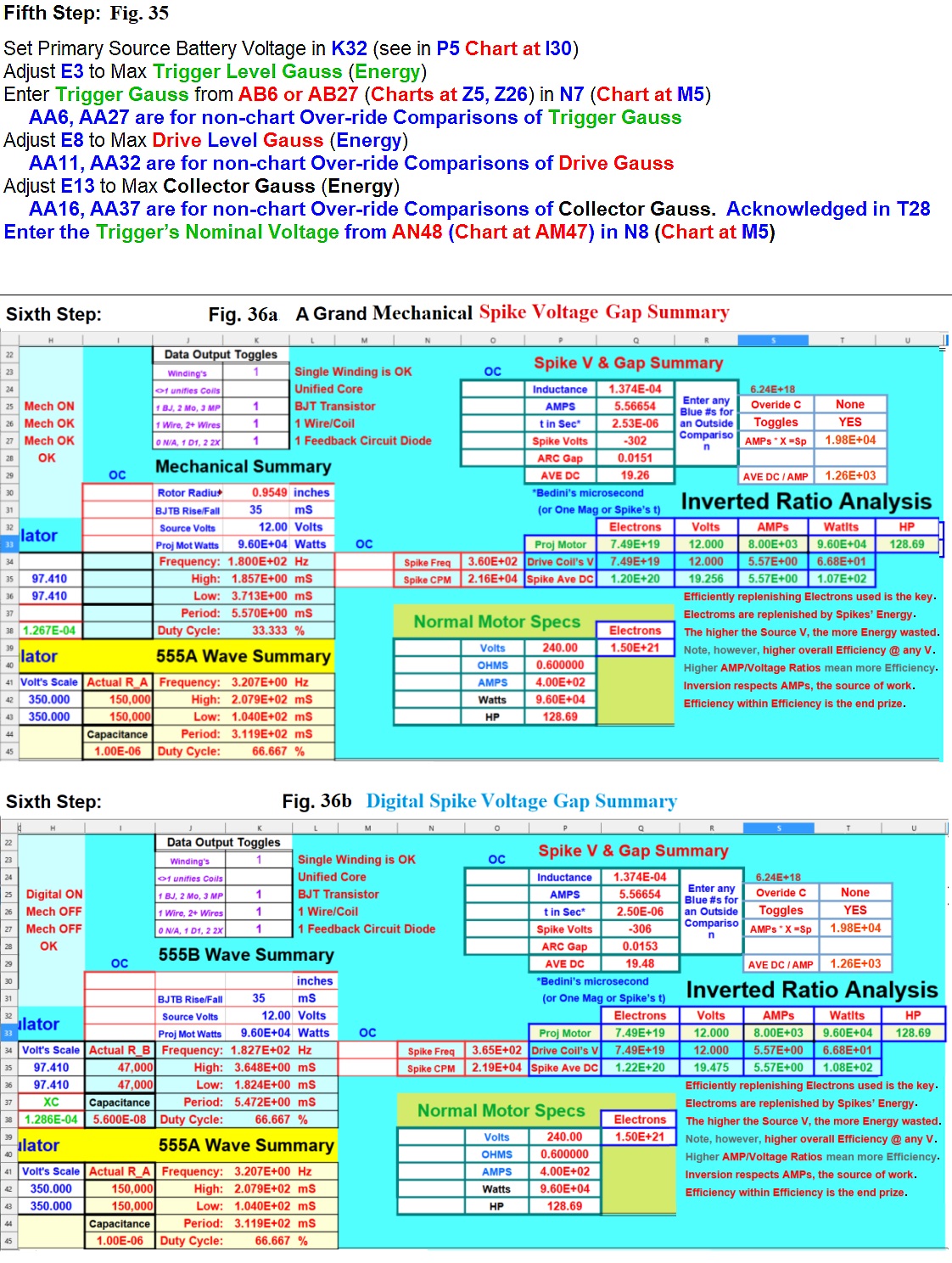
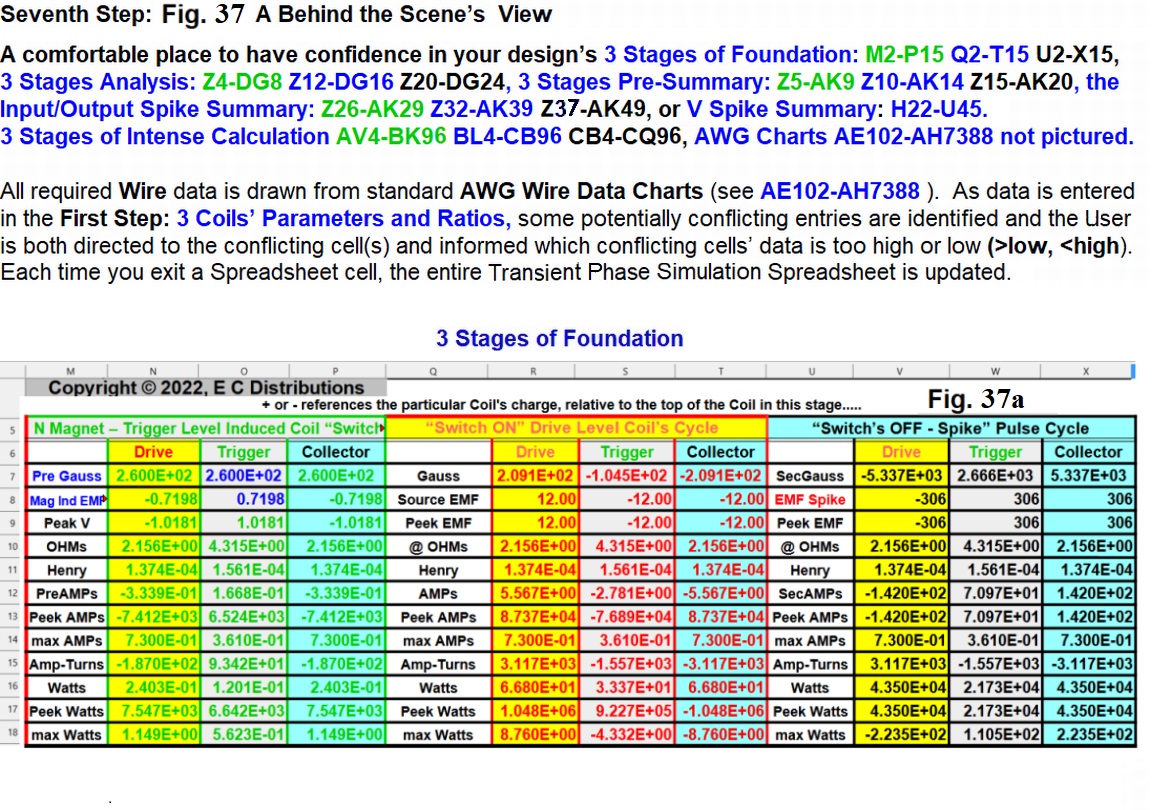
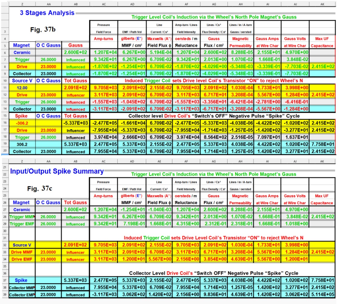
The Sixth Step
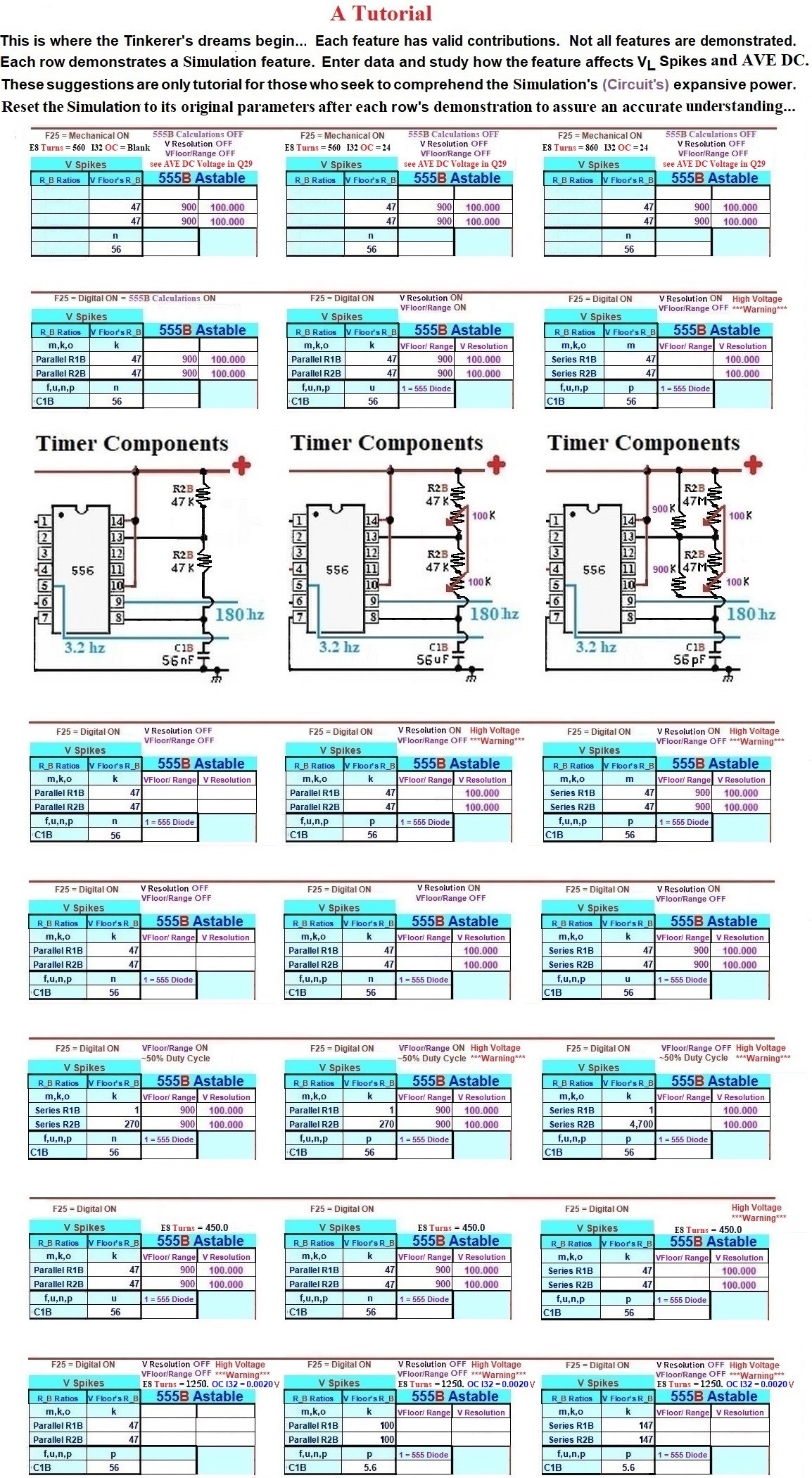
Once a User becomes familiar with the operations of a Bedini Circuit, and is also more aware of what the Transient Phase Simulator is actually capable of doing, the User is going to find the following, mostly repeated information, of great interest. You are now at the stage of the design process to examine what you currently have, and must then fine tune the components to achieve the exact number of Electrons you need to replenish (or sustain) the Source's Electrons that are dissipating each second. It is this type of control that was ignored by those who danced around Tesla's fire. Knowing how many Electrons are being consumed each second is critical to fine tune the Oscillator, that your system can be self-sustaining. The AVE DC must also be taken into account in order to minimize Battery explosions. Differing Batteries' have their own, unique characteristics.
Aside from assisting the User in designing and accurately comprehending what each component contributes, the Transient Phase Simulator literally offers a User the power to analyze any other Bedini type design. The User can zero in on either any Bedini type design's actual function or how the output would be affected by any changes the User may make. The goal is sufficient enough AVE DC VL Spikes to both run your Load and maintain the Source's Voltage. The following list reveals each VL Spike aspect my Transient Phase Simulation offers for consideration before buying components and building a Bedini North Pole Generator.
The Transient Phase Simulation offers all these highlighted Blue Reference features
.....A Higher AVE DC requires either more and/or Higher VL Spikes
........More Drive/Collector Coil Inductance tenders Higher VL Spikes and, therefore, a Higher AVE DC
............Increase B8, (see Wire AWG, Wire's density)
............Increase B9, (# Wires' / Winding (see Wire AWG, Wire's density)
............Increase Source's Voltage, K32, (see R8 and AMPs R12)
............Increase E4, Core's Diameter (see surface area)
............Decrease E5, Coil's Height (see AWG, Wire's density)
............# Drive/Collector Coil's TURNS
................Decrease E8, Drive/Collector Coil's Turns (see AMPs R12)
................Increase E8, # Drive/Collector Coil's Turns (see AWG, Wire's density)
............Increase F28, # Drive/Collector Coils, (see Wire AWG, Wire's density and VL Spike's Hz)
............Two Drive/Collector Coil Windings K23, amplifies Spikes
............Individually wrapped Wires K24, may require more Drive Coil Turns
............Exponential Wires K26, Theory on # Wires Inductive Reactance amplification
........Less Time (t1, t2) precipitates a Higher VL Spike Frequency
............Increasing K25, K31, Lowers Transistor response Time, (less t1)
............Decreasing R1B, B35, Timer, (less t1)
................Decreasing R1B, (1K), relative to R2B, (270K), balances the Duty Cycle (t1, t2)
............Decreasing R2B, B36, Timer, (less t1, t2)
............Decreasing C1B, B38, Timer, (less t1, t2)
............555 R2B Bypass Diode ON, D37, Timer, (less t1, t2)
............Feedback Diode ON, K27, Can double the frequency of the Spike hz Pump VL Spikes, or more
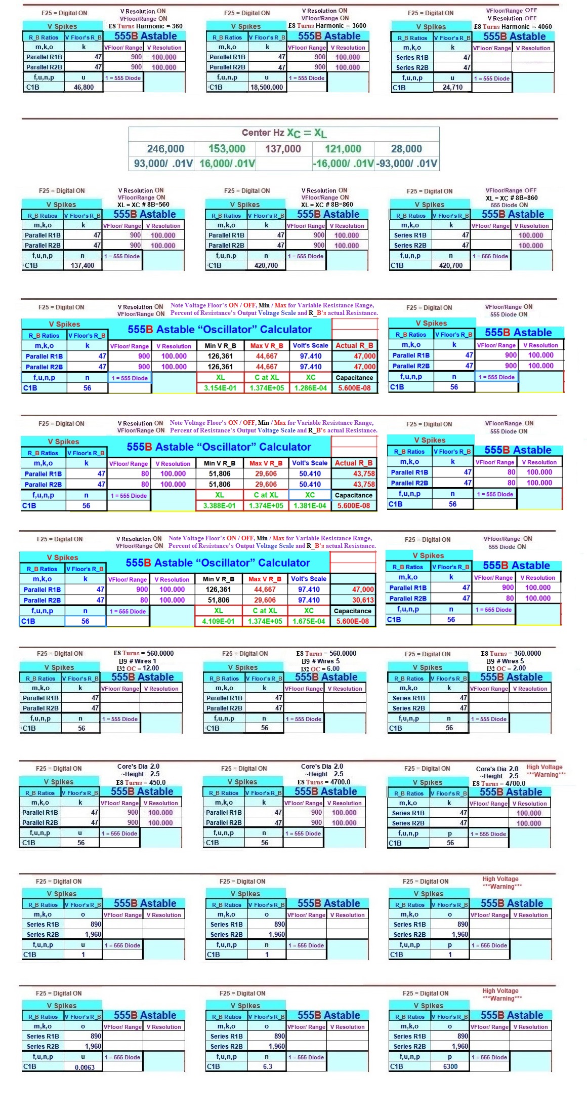
To accomplish this fine tuning, you may also fiddle with the frequency or other aspects you could alter to isolate where you desire to focus your tuning through Over-ride Comparison entries in M34, M35, O24, O25, O26, O27, or O28. IF you choose to use Over-ride Comparisons, do not forget to turn them off. The Field of P33 - U35 encompasses both Primary and Secondary Principles' Inverted Ratio Analysis, with a comparative illustration for the Highest Efficiency within the number of Electrons being consumed per second by each of the three systems: The Projected Motor, the Drive Coil, and the collapsing Magnetic Field's VL Spikes' AVE DC Charging Potential. Focusing on Inductance, Drive Coil's AMPS, Spike hz Electron Pump's frequency and the AVE DC's Potential Charge are key. As the Tinkerer moves Beyond Bedini they will also discover the need to focus on their Components' and Wires' capacities to carry the Intensity of the VL Spikes' AVE DC Charging Potential of their design.
This remarkable Transient Phase Simulation will intensely stun its Users with clarity as they come to appreciate the breadth and depth of useful information it provides Tinkerers.
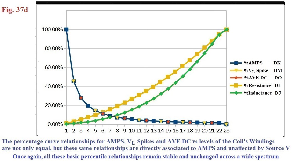
The Transient Phase Simulation's (Circuit's Spreadsheet Simulation) Output highlights both the advantages and disadvantages with respect to either the Mechanical or Digital design formats. It is easier to obtain higher frequencies in the Digital mode, yet the Mechanical mode's "ON" and "OFF" Times are more balanced. My Transient Phase Simulation is a magnificent assistant in either mode. The beauty of the Transient Phase Simulation is in no waiting time to build and the money saved from unneeded parts.
Of note are the amounts of Data the Transient Phase Simulation generates for each Coil: the number of Turns/Level, the Total number of Levels, the Wires' Lengths, the Wires' Weight, the Wires' Surface Area, the Wires' Resistance , the Coils' AMPS and its Henry (or Inductance). My Transient Phase Simulation is a very powerful aid, tutorial and resource for a User to not only comprehend Transient Phase Transformations, but to also design and build many meaningful and operational projects. In numerous ways I was rewarded for my effort in building the Transient Phase Simulation, as the immense amount of information the Simulation offers solidifies a User's comprehension of the Transient Phase.
Along with two powerful and unique sub-sections that cannot be seen when my Transient Phase Simulation is locked, my Animations of several Circuits' operations also contribute to a User's benefit.
The Simulation's first unique sub-section is encountered when more than "1" Wire is chosen at A4, A9, or A14. My Simulation takes each greater than "1" Wire entry, calculates each combined Wire's AWG, and displays these values in B4, B9, or B14. Each distinctly possible AWG is both continuously scaled and linked to a complete, expanded four digit superset of a Wire's Nominal Diameter. Load the Simulation and observe the current Trigger Wire's Surface Area in J6. Now enter "31" at B3 and "3" at B4. noting the dynamic difference in J6. This highlights the Principles' beginnings.
The second unique calculating sub-section is where the Simulation organizes each of the Coils' specific attributes and updates these calculations automatically from User's Input details. These quiet calculations provide a massive amount of information to direct a User's design.

Basic Inductive Principles
Magnetic Flux is analogous to electric Current. Magneto-motive Force, MMF, is analogous to the Electromotive Force, EMF, and, according to traditional thought, is the factor that sets up the Flux. The MMF is equivalent to a number of wire Turns carrying an electric Current and has units of Ampere-turns. If either Current through a Coil
(as in an electromagnet) or the number of Turns in the Coil are increased, MMF is greater, and, if the rest of the Magnetic circuit remains the same, the Magnetic Flux increases proportionally. One Gauss is defined as one Maxwell per square centimeter.