Series 3 Version 7, 2 Winding Digital SG CIRCUIT ASSEMBLY
Series 3 Version 8, 2 Winding Digital SG CIRCUIT ASSEMBLY
Bedini's
focus has always been “Creating Original "Ot" Timed”
Mechanical or 555B's Switch #1 ON Pulses in
the Primary Oscillations' Command Center “as
collapsing Magnetic Fields are allowed to organize”
the shorted Coil's Electron chaos
into “a Higher Electron Energy
Density Intensity”, which is
presented in each Coils' Winding as a VL
Spike (see Figs. 23a, 23b and Coil
Saturation), with Transient Phase B's Spike hz Pump's
555B's Timed Switch #1's
“t2 OFF Pulses” in the Primary
Oscillations' Command Center, then “isolating”
each Coils' individual VL
Spike (that was created by Mechanical or
555B's Timed Switch #1's “t2 OFF Pulses”), “returning”
each Trigger and/or Drive Coils' VL Spike
to the Main Source and
“storing” (or accumulating in
a Capacitor) each Collector Coil's Timed Switch #1's “t2
OFF” VL Spike;
the Bedini Circuit capitalizes on the
Magnetic Field's collapse by injecting an extra,
Circuit Resonant VL
Spike, doubling the Energy produced
in each cycle's expansions and collapses, and
“the Energy accumulated from these two series of VL
Spikes are then delivered from pile C”,
during the Secondary Oscillations' Command Center's Transient Phase
C's 555A Timed t3 Pulse, to
not only Charge the Battery Bank with pile C (accumulation
stored in the Capacitor), but also
end both Transient Phase C and this
Ot cycle's series of Transient Phases, to then repeat the
entire series of Efficient Phases with another Ot cycle at the
Resonant frequency.
Building
What Is Now Simply Known means the Bedini design has been streamlined
and Simplified with both greater Energy Efficiencies and
a higher output potential. My
Transient Phase Simulation accentuates all past and present
Efficiencies in its analysis as you refine each component's
contribution. The Feedback for an
additional t1 Pulse was added, and
another up-scaled design eliminated the need for the Storage
Capacitor, Diode Bridge
and an independent Collector Coil, and
the second Wave Timer along with its components for the Pressure
Relief Valve are also no longer needed.
The remaining components demonstrate the necessities
required to comprehend and explore the features discovered by Tesla.
ALL these features,
characteristics and combinations are readily available
in the Transient Phase Simulation, and
accelerate any serious Fiddlers wildest anticipations of
comprehension and success.
In An Analogy to Summarize the Process in
A Simplified School Girl Events
(Transient Phase Simulation Spreadsheet #1)

In
summary of the One Dimensional process, envision
an individual hired for each Transient Phase's Output Voltage Stage, beginning with every Coil Winding, and ending with the Output Diodes in your Simplified North Pole Generator, every individual with
their own shovel, and each individual's shovel has a
specific size designed for their particular amount of Timed work. These individuals each perform their repetitive task of moving an increasing volume of Electrons (through
the Circuit's design) by Transferring
the VL Spike's Electron Density increases to the next Stage for further processing. These individuals represent the
dynamic design of Tesla's intent to create the higher
Average Density of Electrons required to replace the
Source Volt's Electrons being dissipated or consumed to
power the load. COIL
WINDING SPOOL Specifications
WINDING
THE COILS Label
each Coil's Wire to eliminate error and confusion. BATTERIES,
RECHARGEABLE
Obtain
the Battery manufacturer's data sheets (from the internet).
The following characteristic profile curves are important: Voltage,
Current, Charge capacity and Discharge Capacity.
Your
goal is a sufficient and Higher AVE DC The
Transient Phase Simulation offers all
these highlighted Blue Reference
features. OPERATING
PROCEDURES
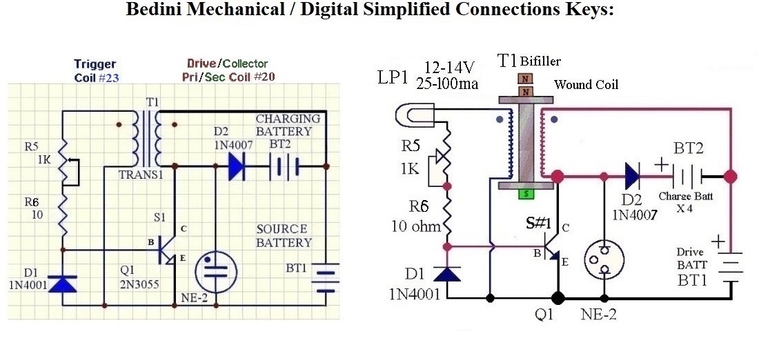
The
Neon Bulb, NE-2, provides a safe path for the Energizer's output
Energy in case the receiving Battery is disconnected while the motor
is running. This prevents burn-out of the Transistor. This light
should not go on unless the Charging Battery is disconnected. Once
the Energizer is configured for optimum operation, connect a fully
charged Source Battery and at least one equal size fully discharged
Charging Battery in the Energy output Bank. Let the Energizer run
until the Source Battery reaches the manufacturer specified minimum
discharge voltage. Measure the Charging Battery capacity by fully
discharging it (to manufacturer's minimum voltage) into a known load.
Compare the Charging Battery Bank capacity to that of the Source
Battery. RAMIFICATIONS
The
worst Battery in the set does not become the weak link in the chain.
CONCLUSION
A
successful replication of the basic Bedini SSG is only the beginning
of the learning process. The next step is to
upgrade to more advanced setups involving all the characteristics
included with My Transient Phase Simulation (multi-strand Coils,
multiple stators, higher frequencies, etc.... Applying this
technology to other fields such as fuel cells is also a possibility.
REFERENCES
The First Shoveler is in Output Voltage Stage #1 for a Series 3 Circuit. The Trigger Coil is where the One Dimensional VL Spike creation (or origination) begins with a half cycle's t1 Pulse. It should be noted that the First Primary Shoveler at the Trigger Coil delivers the First half cycle's t1 Pulse in the "Switch #1's ON Pulse" and Transfers the VL Spike to the Drive/Collector Coil to be processed when the Trigger Coil's Field collapses at t1's Switch #1's OFF Pulse.
The Second Shoveler is in Output Voltage Stage #2 for a Series 3 Circuit. The Drive/Collector Coil is where the One Dimensional VL Spike is directed to be enhanced, (by the Diode Process), which began with a t1's half cycle's Pulse. It should be noted that when the VL Spike in the Drive/Collector Coil collapses, another half cycle's t1 Pulse is generated in the Trigger Coil to create a Second VL Spike in the Drive/Collector Coil. The Second Shoveler is performing double duty, as another VL Spike is then Transfered to the Drive/Collector Coil to be processed when the Trigger Coil's Second Field also collapses at t1's Switch #1's OFF Pulse.
The Third Shoveler is in Output Voltage Stage #3 for a Series 3 Circuit. Diode #3 is where the One Dimensional VL Spikes are enhanced and are then each moved in the Two half cycle Pulse sequencea to the Output Battery Voltage Charging Stage during t2's half cycle's Pulse.
Guidelines for constructing
A Simplified School Girl
(Transient Phase Simulation Spreadsheet #1)
Plastic, 3" diam. by 3" long, with an open, 3/4"
Core.
Tolerance
Core
needs to be +/- 20%. Length of spool can be +/- 40%. Material needs
to be low Reluctance, non-metallic, non-Magnetic, and adequately
sturdy. These Tolerances are unique from the School Girl
Motor/Generator. My Transient Phase Simulation gives an intense
insight to how the attributes of Inductance affect VL
Spikes.
Coil's Electromagnet Core
Coil's
Electromagnet core material to propel Magnets along as the
Electromagnetic core is pulsed by each Magnet of the Wheel and also
the extra Feedback Pulse Circuit.
Welding Rod
0.042" diameter copper coated steel rod. 3 foot lengths.
(will be cut to the length of the Coil's core. Get 3-5 lbs. (around
10 rods of 3 feet each).
Rough cut is okay. Diameter is
not crucial, and could be smaller by 50% or larger by 100%. Available
at your local welding supply store (such as Oxyarc) or hardware store
(such as True Value or Ace or an auto parts store). Estimated Price
$0.60 per rod. The thicker the rod, the harder it is to cut. You're
going to be cutting a lot to fill the spool's core.
Filling
The Coil's Electromagnet Core
Be sure the
rods in the Coil's end that will be facing the Magnets, are flush so
your Magnets' Wheel spins without hitting either a core's rod or the
spool
If you drill a 1" hole in the core's base about
1/2" deep, you don't have to cut your rods shorter.
Use
glue on each rod to fill the spaces and keep them from moving.
Tap
the last few rods in with some light object until no more rods fit.
Wind the Coil's two Wires on the spool together.
It is very
important that the Coil's two Wires be next to each other the entire
distance of the winding.
Fill the spool. Approximately
450 to 900 Turns.
You may use a drill to spin the spool.
A variable speed drill offers more control, making it easier to count
Turns and ensure the two Wires are wound parallel the whole distance.
John says the exact number of Coil Turns is not crucial
to operational success. Close is adequate. Symmetrical windings are
not crucial. Think fishing or kite spool.
The Circuit's window of winding tolerance is very wide. However, an
exact count and Wires' lengths will be necessary for scientific rigor
in documenting, calculating, analyzing and
reproducing precise results.
One
additional update on the Coil (T1). Cut 150 to 350 feet of
each wire (same length). You can use two #18 size wires at 150 feet
instead. Instead of winding two wires in parallel, twist the two
wires like Litz wires. For the smaller size wires you can have 6 or
more twists per inch. Don't twist too much or they will break. Then
wind it as you would have any other wires.. . Use the parts listed.
You can use Transistor #1 BD243C, as found in John's patent, in place
of the one listed.
Counting visually is nerve-wracking
and prone to error. Use an audible trigger in winding (e.g. a clacker
on the spool). Alternatively, you might affix tape to both ends of
the spool, protruding outward around 1/2". This tape will hit
your hand as the spool rotates, helping you count Turns.
The
powering Source of the Energizer Circuit Motor/Generator, and
Batteries receiving a Charge from the Circuit (Source and output need
to be different Batteries; closed loop will not work).
Battery
Specifications
6 to 24 volt
Batteries are functional, however, At least two 12-volt lead acid
Batteries are recommended. One for Source, one for Charging. More are
recommended for experimental options.
Tolerance
The
Battery's voltage rating is not crucial, and can be in the range of 6
to 24 volts for this particular Energizer Circuit/Motor Generator
design. Bedini recommends getting 10 new or used Interstate 6v golf
cart Batteries and make 5 12v batteries. However, Source and Charging
Batteries need to be matched in their voltage and impedance (size).
There can be more than one Charging Battery on the receiving end,
connected in parallel, if each Charging Battery matches the voltage
and impedance (size) of the Source. For your first replication, use
new Batteries to eliminate (minimize) reasons for Circuit
malfunction. Not all rechargeables are suitable for receiving
this type of Charge. Lead acid recommended.
One 1N4007 to Each Battery
in the Charging Bank
Dec. 9, 2004
http://groups.yahoo.com/group/Bedini_SG/message/431 Peter and John
recommend that we set up our 1:4 Battery arrangement according to the
following:
Isolate each
Source matching Battery in the Charging Bank
In
addition to the 1N4007 Diode coming from the Circuit to the first
Charging Battery's positive terminal, branch off to each Charging
Battery with a 1N4007 Diode so that each Charging Battery is seen
independently. (Once again, a lower Resistance). Note Harlan
tried omitting the Diode coming from the Circuit, just using one
going to each Battery, and that did not work.
You may
branch out your Charging Circuit from D2's Positive connection with
either a single D2 Diode to each Charging Battery, or you can
parallel one or more identical D2 Diodes for each Charging Branch.
Just make sure all paralleling D2 Diodes polarities are correct (to
make one big Diode for each Branch). If using 5 Diodes per 4 Battery
Charging Branch in a 5 Battery Charging setup (1 powering Battery and
4 Charging Batteries) you will have 5 x 4 = 20 D2 Diodes total. Hint,
D2's in parallel, and parallel Charging branches both have
independent effects of lowering Resistance.
Battery
Care
It is important to know your
Battery manufacturer's optimal operating parameters so you do not
inflict damage by Charging or discharging them too fast or too
high/low. You will not need to worry about speed or level of Charging
while using the Bedini Simplified School Girl Circuit. But if you use
another Charging apparatus, you need to know your Batteries'
characteristics and Charging parameters. If your Source and
Charging Batteries are matched in voltage rating and impedance (size)
the Circuit inherently balances the Charging rate to a level that is
not only safe, but even beneficial to
the Charging Batteries. Overcharge with
the Simplified Bedini School Girl Circuit is not nearly the concern
it is with other chargers. Batteries
charged with the Bedini Simplified School Girl Circuit actually
perform better under frequent use than letting a few idle days pass.
When your Charging Battery is identical to your Source
Battery, this is a Control.
(1) This Control allows you to test
the discharge parameters of a Battery, independent of the Circuit and
under the same discharge parameters.
(2) Additional Batteries
of the same voltage and impedance can be added to the output in
parallel.
(This ratio scenario graphically demonstrates there
can be more Energy put out than the Source has put in).
(3)
This same Energy ratio can be the widest and most crucial variable in
the Energizer system.
....A Higher AVE
DC requires either more and/or Higher VL
Spikes
........More
Drive/Collector Coil Inductance tenders Higher VL
Spikes and, therefore, a
Higher AVE DC
............Increase
B8, (see Wire AWG, Wire's
density)
............Increase B9,
(# Wires' / Winding (see Wire AWG, Wire's
density)
............Increase
Source's Voltage, K32, (see R8
and AMPs R12)
............Increase
E4, Core's Diameter (see surface
area)
............Decrease E5,
Coil's Height (see AWG, Wire's density)
............#
Drive/Collector Coil's TURNS
................Decrease
E8, Drive/Collector Coil's Turns (see
AMPs R12)
................Increase
E8, # Drive/Collector Coil's Turns (see
AWG, Wire's density)
............Increase
F28, # Drive/Collector Coils, (see Wire
AWG, Wire's density and VL Spike's Hz)
............Two
Drive/Collector Coil Windings K23,
amplifies Spikes
............Individually
wrapped Wires K24, may require more
Drive Coil Turns
............Exponential
Wires K26, Theory on # Wires Inductive
Reactance amplification
........Less
Time (t1, t2) precipitates a Higher VL
Spike Frequency
............Increasing
K25, K31,
Lowers Transistor response Time, (less t1)
............Decreasing
R1B, B35, Timer,
(less t1)
................Decreasing
R1B, (1K), relative to R2B,
(270K), balances the Duty Cycle (t1, t2)
............Decreasing
R2B, B36,
Timer, (less t1, t2)
............Decreasing
C1B, B38,
Timer, (less t1, t2)
............555
R2B Bypass Diode ON, D37,
Timer, (less t1, t2)
............Feedback
Diode ON, K27, Can double the frequency
of the Spike hz Pump VL Spikes, or more
Plan
the entire experiment before purchasing components. My Transient
Phase Simulation was designed to assist Tinkerers in every way
imagineable, and it is very useful.
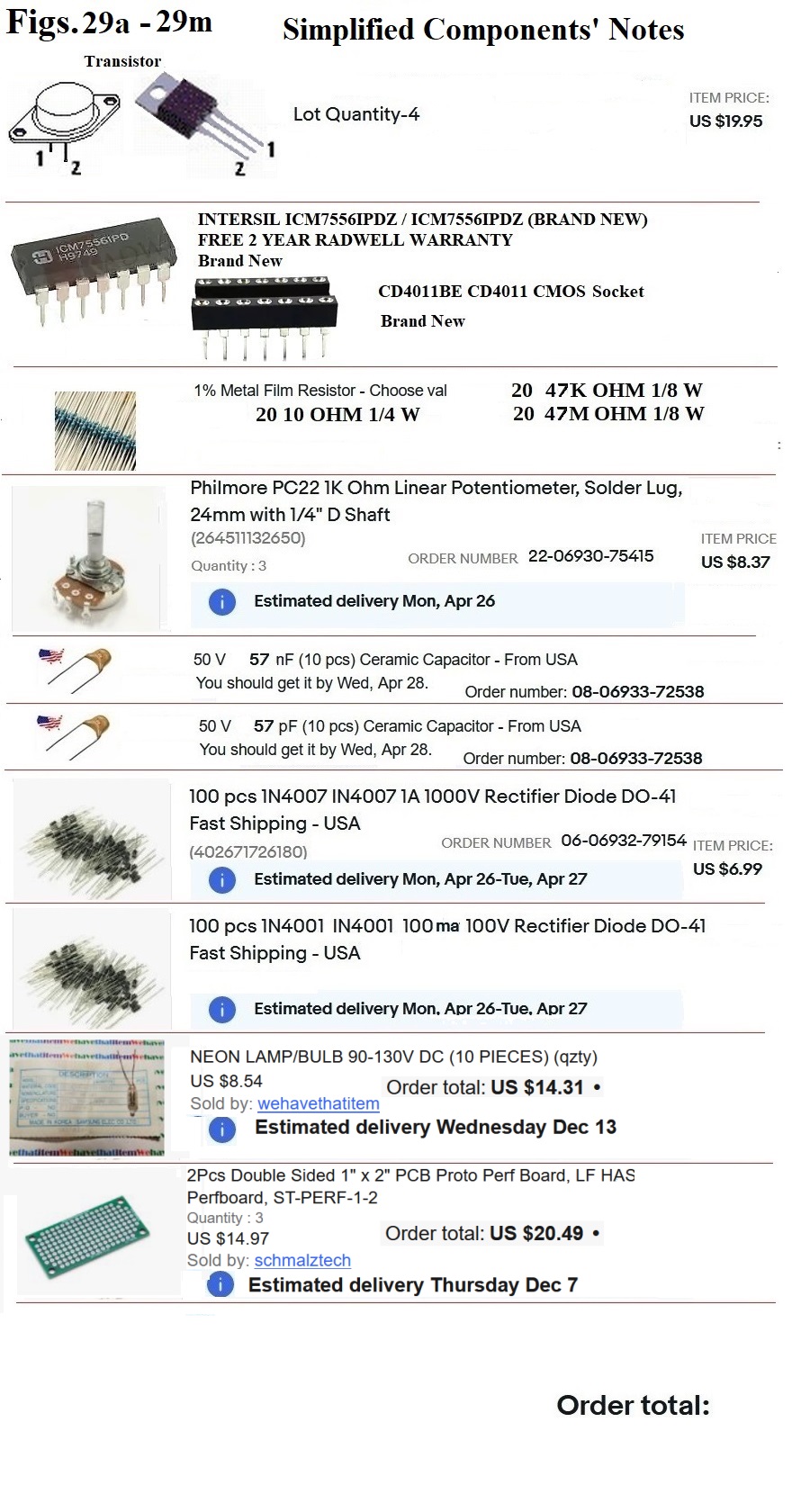
Neon
Bulb (NE-2) Specifications
Chicago Miniature Neon Base
Wire Terminal T-2 65VAC .6mA NE-2, One, 90-Volt DC Neon Bulb. A1A by
Chicago Miniature See also Lumex P/N GT-NE3S1025T, lumex.com
http://www.lumex.com/product.asp?id=1000657 .
CAUTIONS
Dangers
associated with this project are mainly with the Batteries, but
soldering and Wheel rotation are also considerations. Be sure you
understand the risks and take necessary precautions.
While
this design can deliver some good shocks, the
shocks with these specific component values are not,
generally, of a
dangerous level.
This device
/ Energizer Circuit should not be operated without a receptacle for
the Energy (e.g. Charging Battery). The
Neon Bulb (NE-2) is protective and
cautionary, and does not light up under
normal conditions. If the Neon Bulb is not in place, the
Transistor is likely to be burned out by the VL
Spikes. The Neon Bulb absorbs the
transient Energy like a shock absorber (or a necessary defuser
that is neither "tripped" or needs to be reset).
Over
Unity Evaluation
Evaluate your Energizer's performance
for Over Unity after Charging discharged Batteries from a fully
Charged Battery, and analyze the ratio for the amount of Energy
extracted from the Source Battery with the amount of Energy in the
Charged Battery.
Operating the
Motor / Generator
To run the Motor / Generator, connect
the Energizer Circuit to the Source and give the rotor a spin (by
hand or some other external mechanical force). It will then
accelerate or decelerate to a point of equilibrium. At some
Resistances in the Circuit, there will be more than one stable rate
of rotation.
Tuning the Motor /
Generator
Tune Circuit / Motor to its lowest current /
highest RPM sweet spot (or Resonance) by adjusting the Pot from its
lowest value, up till the additional pulses start to flicker LP1 and
Drive Current increases, then back off a little. till the extra
pulses stop, and let the RPMs stabilize before any more tweaking is
done. When the extra Feedback pulses show, LP1 will flash.
The
Circuit needs a sufficient Wattage Potentiometer (or Pot). Pick ma
size of LP1 that will not allow additional Feedback pulses when the
Pot is at its lowest value (because of LP1's Resistance), but not so
high a Resistance that LP1 will not allow a flickering Feedback near
the motor's sweet spot of Resonance.
With the Energizer
running, adjust the Base (see Transistor #1's Feedback Pulse @ R5)
Resistance for minimum Source current draw and VL Spikes'
(AVE DC) voltage. It is important that Motor / Generator Circuit
operation is sustainable at your component's values.
PERFORMANCE
EVALUATION and TIPS
In functional application, you should not draw
power from a Battery that is presently being Charged. You should have
one Bank of Charge Batteries, and one Source Battery for discharge,
and switch them.
Performance
Once
you have confirmed your Energizing system is functional, beef
up your connections to lower Resistances and optimize Efficiency.
Use a heavy gauge wire and terminal connectors with crimping. The
above photo shows a set-up for rotation of Batteries from the back to
the front, allowing for single Battery Charging (fresh from the
front) while that Battery comes up to the same voltage as the rest of
the Charging Bank, so they can then be connected in parallel.
TUNING (or Adjusting Resistance to
find Resonance)
Note that the
arrangement includes a switch to enable meter readings without
extended disconnection of the Circuit. Depending
on how responsive the meter is, the Circuit is interrupted for
maybe one or two seconds using this method.
The 25 Ohm
Resistors give a fine-tuning capability. The bread board enables hard
Resistor plug-in for the range desired. The 5k Ohm Pot enables a wide
berth of tuning. Note: the 5k ohm Pot tends to
be unstable at holding a Resistance. If you wish to lock into
a particular Resistance, you should consider inserting a desired R,
bypassing the 5K Pot.
No need to stop the Circuit when rotating Batteries.
No
need to have the Bank standing idle, discharging while the Battery
from the Source comes up to charge.
When the Source
Battery discharges, the Battery with the highest charge from the Bank
(not necessarily the one that has been there the longest), can be
brought to the front to run the Circuit NB.
Either any of my Transient Phase Simulations or the CircuitMaker Program are using Excel
(or Spreadsheet type techniques) for their intense calculations.
It is, therefore, advisable and wise to know Three things:
Any of these resources files can be corrupted if your
computer's resources are over-taxed.
and a requirement to use any of the Transient Phase Simulations is to have Excel or an equivalent.
Preserve Original File, and Work only from a backup to avoid File corruption when using these resources, and be vigilant protecting your work.