 ---------
Copyright © 2008, E C Distributions
eternaltruth.net
is dedicated to both comprehending this
obscure concept and successfully designing and then constructing a
Bedini Mono-pole (North Pole) Motor, which is a very Efficient
device based upon principles discovered by
Nikola Tesla and heavily researched and developed by John Bedini.
John assisted a young School Girl over the phone as she built a North
Pole Motor for a science fair project. The Bedini Mono-pole Motor
concept has become synonymous with the Bedini Generator, the School
Girl Motor, the SG Motor, the School Girl Motor / Generator, or the
Simplified School Girl Motor. Every major thing this Web Site focuses
on is rooted in a Transient Phase.
This particular Page
is dedicated to the all North Pole Motor. The LED represents the
extra generated Energy. She built this
Motor all by herself and took all the first place ribbons plus a
special award in science. It used a 9V battery and ran five full days
at the science fair before they stopped it.
---------
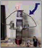
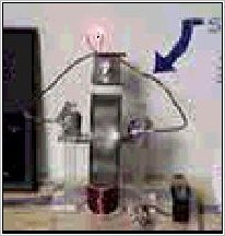
Two stills from the video showing the Motor operates from a single 9V Transistor battery and is also running a generator that lights the LED on top.
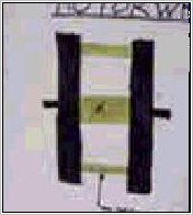
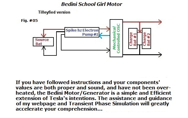
A diagram of the Motor / Generator showing the Magnets between two cylinders, which are forced to spin when the Drive Coil at the bottom is pulsed by the 9V battery and the Coil at the top generates current to pulse the LED. This is only an introductory stage to what Bedini knew of Tesla's concept.
As the wheel rotates, each Magnets' North Pole (mounted between the discs) induces Current during each Magnet's approach to the Trigger Coil, which momentarily turns "Switch #1 ON" for the 9 Volts to the Drive Coil, which introduces the "Primary Oscillations' Command Center," where each wheel's North Magnet is repelled, and the Voltage (VL) Spike resulting from "Switch #1's OFF" recharges the battery and the Collector Coil sends VL Spike's Energy to illuminate the LED.
A 1.5 V DC slot car motor easily draws from 200 milliamps (300 milliwatts) to 500 milliamps (750 milliwatts). 4000 rpm with this kind of power usage should NORMALLY drain a 9V battery in a couple of hours.
John says this motor/generator ran for 5 days (120 hours!!) on the single 9V battery. That is amazing and the girl should be congratulated for demonstrating the concept to win the science fair awards.
John wonders what is wrong with the world if a School Girl can build one of these and win a Science Fair?
Build your own Motor and prove the concept for yourself.
This
battery was measured at 8.9 Volts by the science teacher before the
Motor was turned on.
These are usually 400 milliamp/hour
batteries.
The motor was running on 22 milliamps at 4000 rpm.
When pulling the generator load the current draw on the battery
dropped 8.8 milliamps, down to 13.2 milliamps;
.
John
has been working with these types of Motors for a very long time. He
has said all along, when these Motors are built like he has stated,
not changing anything until after you have witnessed the same
results, you will have no problem replicating or furthering his
designs. John's vision is to change the world through children,
because they are willing to learn. The "Educated"
focus on what they have "learned" and change
things to complement that which they have been instructed to think.
John Bedini claims to have a Motor in his shop that has
been running on the same batteries for 12 years.
If people
would just build these Motor circuits the way he describes, they will
obtain the same results he has claimed, and then they could make
other improvements and we could become Energy
Efficient. My Spreadsheet Simulation is
an amazing tool and spectacular tutorial for anyone who is seriously
intrigued with this concept and wants to comprehend the entire scope
as it is now known.
John courteously has both sent and
given permission to post this cool diagram of the School Girl built
Motor. If you choose to build this very simple Motor.
Series 3, Version 1
a better drawing I made of Series 3, Version 1
and this is my understanding of this Series 3, Version 1device.
Q1
(Switch #1)
is an MPS8099 or a 2N3055 (both bipolar Transistors).
R5 is a 1K
Resistor,(.variable Resistor, or Potentiometer)
R6 is a 10 ohm
Resistor.
D1 is a 1N914 or a 4001 Diode.
D2 is a 4007
Diode.
John also cuts his welding rods to the length of the
coil form, then inserts them into the center hole around which the
wire is wrapped to form the coil.
An 'iron' core transformer
increases the Magnetic Flux.
John released the
information in the following diagram
to show the Transistor and
component arrangement to also clarify some aspects of the design.
I
have combined two diagrams into one, and color coded the Windings.
Dual
Battery Motor Series 3, Version 2
courtesy John Bedini
Series 3, Version 2
Make
no mistake.
You can see by the accompanying Oscilloscope
depiction that there is a sharp Voltage
Spike (VL).
For those who are unfamiliar with Transistors, the Transistor
in this schematic is acting as Switch
#1.
The VL
Spike is occurring when
the Transistor (or Switch #1) is
opened,
just like I have portrayed in the "Intro
to An Energizing World of Mysterious Charges" section of
this Web Site with the Neon Bulb (or
NE2).
Consider the potential, pun was intended.
This
Web Site is dedicated to taking the world far beyond what either
Bedini or Tesla knew.
My
Transient Phase Simulation will expand any comprehension of this
concept immensely.
Either any of my Transient Phase Simulations or the CircuitMaker Program are using Excel
(or Spreadsheet type techniques) for their intense calculations.
It is, therefore, advisable and wise to know Three things:
Any of these resources files can be corrupted if your
computer's resources are over-taxed.
and a requirement to use any of the Transient Phase Simulations is to have Excel or an equivalent.
Preserve Original File, and Work only from a backup to avoid File corruption when using these resources, and be vigilant protecting your work.
Return
Home